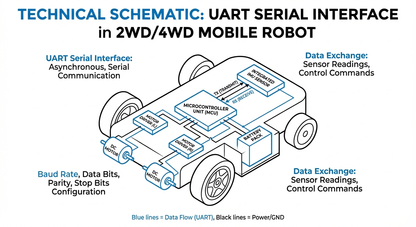
UART Serial Interface
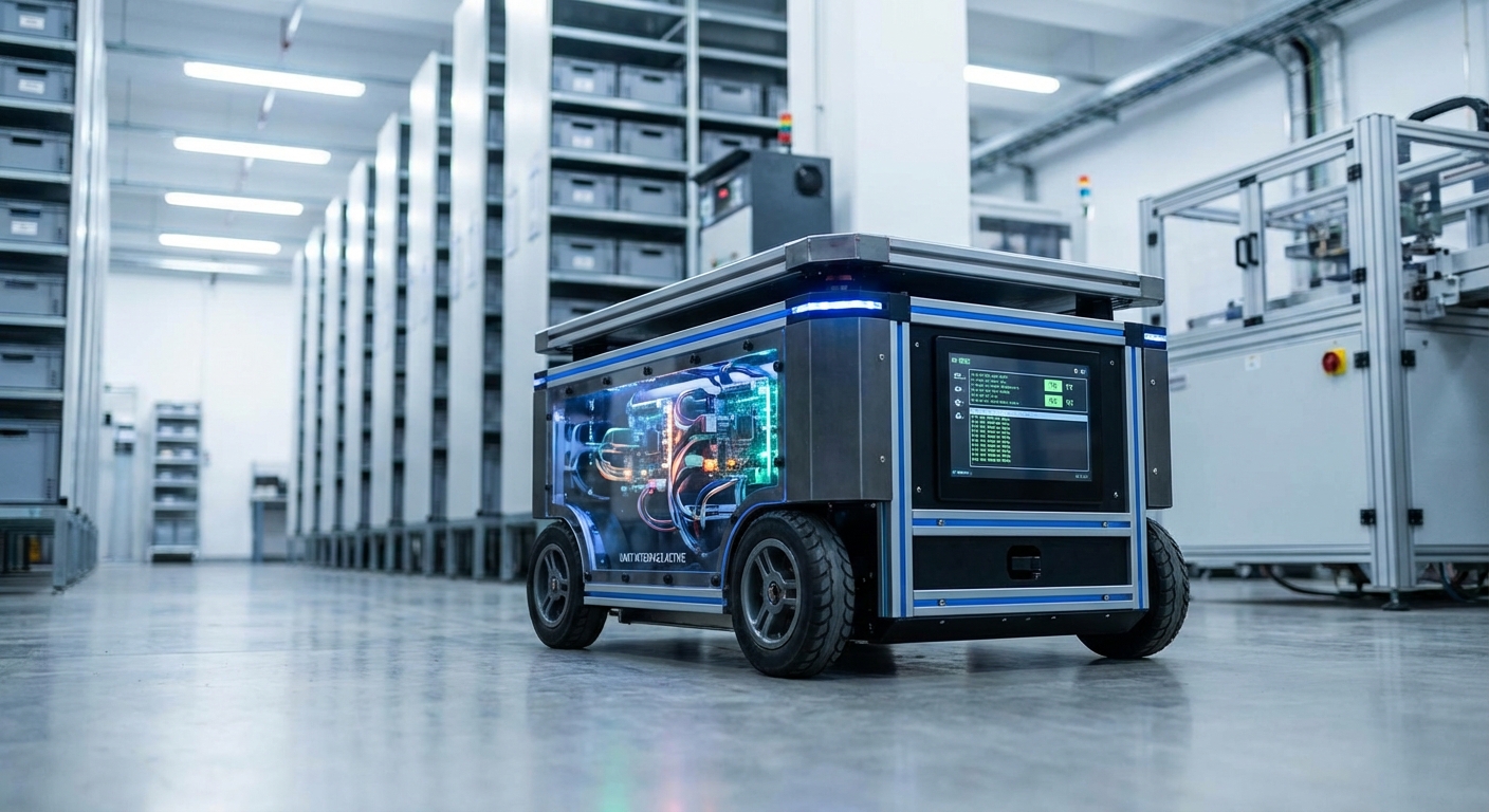
The Universal Asynchronous Receiver-Transmitter (UART) is the core protocol connecting microcontrollers to sensors and modules. It's the trusty 'nervous system' for AGVs, handling motor drivers, GPS, and telemetry with precision.
Core Concepts
TX & RX Lines
It runs on two wires: Transmit (TX) and Receive (RX). One device's TX plugs straight into the other's RX for straightforward point-to-point chat.
Baud Rate
That's the data speed in bits per second (bps). Devices must match baud rates exactly—like 9600 or 115200—to read each other right.
Asynchronous
Unlike SPI or I2C, UART doesn't need a shared clock signal. It handles synchronization with start and stop bits, which keeps wiring simple for mobile robots.
Data Packets
Data travels in small packets, usually 8 bits. Each one starts with a low start bit and ends with one or more high stop bits to keep everything reliable.
Voltage Levels
Logic levels depend on the setup. Microcontrollers often use TTL (0V to 3.3V/5V), while industrial standards like RS-232 go with higher voltages (-12V to +12V).
Parity Bits
It includes an optional error check: a parity bit added to the packet to make the total number of 1s even or odd, catching single-bit errors.
How It Works
UART is a key part of robotic setups because it's so straightforward. When a host like a Raspberry Pi or STM32 wants to send a command, it pulls the transmit line low for a "Start Bit," waking up the receiver.
After the start bit, the data bits (usually 8) follow one by one, starting with the least significant bit. This is your actual command, like a speed vector for an AGV wheel or a set of coordinates.
Then the line goes high for the "Stop Bit," signaling the packet's done. Timing relies on the baud rate you've set, so even small clock differences between devices can lead to garbled data—precise setup is crucial.
Real-World Applications
LIDAR Navigation
Many 2D LIDAR sensors for SLAM (Simultaneous Localization and Mapping) send streams of distance data to the main computer over high-speed UART links.
GPS/GNSS Positioning
Outdoor autonomous mobile robots use GPS modules that spit out NMEA sentences—standard ASCII strings with latitude and longitude—purely over serial ports.
Motor Control Units
High-level fleet management computers talk to low-level motor drivers via UART, sending target RPMs and getting encoder feedback in return.
Wireless Telemetry
Radio modules like XBee or LoRa for remote monitoring and emergency stops in warehouses work like "wireless serial cables," passing UART data over the air seamlessly.
Frequently Asked Questions
What is the difference between UART, I2C, and SPI?
UART is asynchronous and point-to-point (one-to-one), needing just two wires without a clock. I2C is synchronous, handles multiple devices on a two-wire bus (SDA/SCL), but it's slower overall. SPI is synchronous too and the fastest, but it needs more wires (clock, data in, data out, chip select) per device.
What happens if the baud rates are mismatched?
If the transmitter and receiver baud rates don't match, bit sampling timing drifts. That leads to "garbage" characters or framing errors, where data bits get mistaken for start or stop bits. Communication breaks down completely until the rates line up.
How long can UART cables be in an industrial setting?
Standard TTL UART works best for short runs, like between chips on the same board or quick interconnects (under 30cm). For longer distances across an AGV or factory floor, convert to RS-232 (up to 15m) or RS-485 (up to 1200m) to fight noise and voltage drop.
What is Hardware Flow Control (RTS/CTS)?
RTS (Request to Send) and CTS (Clear to Send) are extra lines to avoid buffer overflows. The sender raises RTS first and waits for CTS from the receiver. This is vital in reliable AGV systems where delays can happen.
Can I connect a 5V sensor to a 3.3V Microcontroller UART?
Usually, no. Hooking a 5V TX to a 3.3V RX pin that can't handle it will fry the microcontroller. Use a logic level converter or voltage divider to step down safely.
What is the "framing error" often seen in diagnostics?
A framing error happens when there's no valid Stop Bit where expected. It's typically from baud rate mismatches, bad noise on the line, or an unsteady clock in one device.
Is UART capable of Full Duplex communication?
Yes. With separate TX and RX wires, data flows both ways at once. This lets an AGV send telemetry while grabbing new commands on the fly.
Why do we swap TX and RX when connecting two devices?
One device's output has to hit the other's input. So Device A's TX goes to Device B's RX, and vice versa. TX to TX? No chat happens.
What is the standard configuration (8N1)?
"8N1" is the go-to setup: 8 Data Bits, No Parity, 1 Stop Bit. Most robotics gear defaults here, so you just tweak the baud rate.
How do I debug a UART connection?
Grab a USB-to-TTL serial adapter and fire up terminal software like PuTTY or CoolTerm on your PC. For timing and logic deep dives, a logic analyzer or oscilloscope shows those square waves clearly.
Can UART be used in a noisy factory environment?
TTL UART picks up EMI easily from motors or welders. In factories, shield your cables and switch to RS-485 (differential signaling) to wipe out noise.
Does UART support multiple devices on one line (Daisy Chaining)?
Not natively—it's point-to-point only. For multiple devices on one port, add a multiplexer or go RS-485 for multi-drop support.